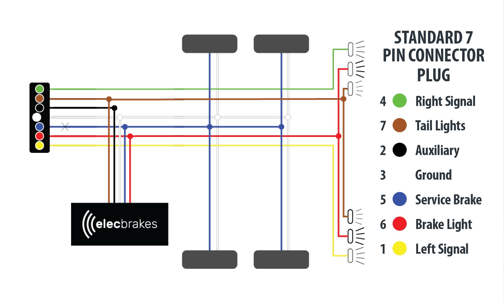
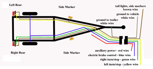
Wiring Diagram For Trailer Lights And Electric Brakes

Rj11 Socket Wiring Diagram Australia, How to punch down an RJ11 Telephone Jack, 6.36 MB, 04:38, 387,634, CableSupply.com, 2009-08-05T00:16:07.000000Z, 19, Rj11 Socket Wiring Diagram Australia | Computacion, Redes de computadoras, Computadoras, www.pinterest.com.mx, 728 x 783, jpeg, rj11 wiring rj45 diagram cable ethernet usb jack pinout adapter cat5 female male convert using rs485 cat wires code socket, 20, rj11-socket-wiring-diagram-australia, Anime Arts
Brakes trailer electric wiring brake diagram wire plug battery schematic installing way dexter utility code trailers dump colors enclosed controller. Wiring kit for 2, 4, 6, and 8 brake electric trailer brake controllers Wiring trailer diagram diagrams brakes electric brake wire rv camper ground lights trailers travel etrailer light way side tip flat. Wiring trailer diagram way plug semi brakes electric test blade brake hopkins pigtail controller electrical circuit.
Trailer wiring diagrams trailer wiring connectors various connectors are available from four to seven pins that allow for the transfer of power for the lighting as well as auxiliary functions such as an electric trailer brake controller, backup lights, or. The following page contains information about trailer to vehicle wiring diagrams including: 7 wire trailer circuit, 6 wire trailer circuit, 4 wire trailer circuit and other trailer wiring diagrams. 7 wire circuit trailer wiring diagram 6 wire circuit. Click to enlarge expert reply by: Brint h ask the experts a question >> products referenced in this question circuit tester kit The master cylinder is mounted on the front of the trailer so any tow vehicle can tow the trailer. Simply put, when the inertia force of the tow vehicle's braking action activates the master cylinder in the surge coupler, the trailer brakes are activated. The other type of brake system is electronically controlled electric brake control wiring.
Wiring Diagram For Trailer Lights And Electric Brakes | Trailer Wiring Diagram

Wiring Diagram For Trailer Lights And Electric Brakes | Trailer Wiring Diagram

Wiring A Trailer With Electric Brakes / Trailer Wiring Diagram - Lights, Brakes, Routing, Wires
Trailer Brake Wire Diagram - Installing Electric Brake Controls on 24 Volt Vehicles | etrailer
Wiring A Trailer With Brakes : 7 Pin Round Trailer Plug Wiring Diagram Nz | Wiring Diagram
Wiring Trailer Electric Brakes / Dexter® Electric Trailer Brakes (White Wire) - RH : In the

11 Brilliant Wiring Diagram, Trailer Brake Lights Images - Tone Tastic
Wiring Diagram for Utility Trailer with Electric Brakes Gallery

Electric Brake Trailer Wiring Diagram - Collection - Wiring Diagram Sample

Wiring A Boat Trailer For Brakes And Lights
